Monday, March 9, 2009
Monday, February 23, 2009
Monday, February 16, 2009
Wednesday, February 11, 2009
Wednesday, February 4, 2009
Monday, February 2, 2009
Triangulated Lattice


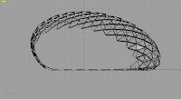
Over the past few days I have been working on a triangulated latice system. This has been the result so far. Based on the Paneling tool plugin. I used the grid from there and worked off the edges and created the pipes along those surfaces. This created an intersting profile however this system increased the amount of pipes needed and in addition increased the complexity of the connection from the square grid before.
Wednesday, January 28, 2009
Lattice


So here is my quick attempt at creating a lattice structure. I used the Contour command to create a series of sections through the surface and then used the pipe command to create this lattice structure. This however created a "square" organization for the node arrangement... This means I will need to rework the node if it were to stay in this configuration.
Tuesday, January 27, 2009
Node Attachment
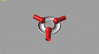
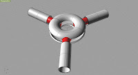
So working through the node attachment. I started to think about how the joint could be flexible. So starting from a equal spacing on the triangle of 120 degrees between each attachement point. I wanted the attachement to rotate about a point so I thought that a circle with a track for something to ride in. Then I needed the attachement points to pivot in the Z direction so I figured that a sphere could pivot in the track and thus give it movement. Then another track sits on the top to anchor the 3 pivot points in the track and then that get clamped down with the a small disc and a bolt.
Establish a Uniform Surface
Establish a Uniform Surface
So with a quick hint from Axel last night after class I was able to get the surface into a uniform surface to work from. As he said sometimes you have to rebuild some things... I guess this is just part of the process.
So here is how I came up with a uniform surface.

This was after doing the SectionCut command in both the X and Y directions. This seemed all good... but the individual surfaces made the curves to be individual as well so the next step was to Join the curves together.
So this was after joining the curves that run in the X direction together... Not much to it just join the lines in the same section cut together.

So after doing that.. I tried to Loft the set of section cuts... but alas came up with a vary weird surface because the edges are not closed.. So I thought well maybe if I closed the loops where all the end fragments of the section cuts that would do the trick.. So I spent a few minutes and did that as well.. Its hard to see in the picture but you can see the edges closed on the right side of the photo.
So this shows the "Cut edges" with the curves extracted from it. So after having the Edges in the mix again I tried to loft again using all the of the section cuts curves... but still this was producing weird surface results. So after a bit. I just used the highest section cut and then the two edges and came up with a Lofted Surface that resembled the one that we started with.


Well I made it to the end... The lofted surface in the Red was after lofting the 3 curves that I extracted from the original polysurfaces. So it seemed like it was a good fit. So I overlaid the two surfaces to see if there was a difference. You can see the red stripe on the final overlaid lofts. However this is just a minor difference and mostly a graphics issue. So now I have a solid Surface to work with.
Hope this helps others out there.
Monday, January 26, 2009
Thursday, January 22, 2009
Monday, January 19, 2009
New Stuff
This example is a more traditional system for creating a space frame system. This node has ports in which the threaded posts screw into. 

After doing some more digging around came across this example. This model focused on the node of the system as a means to create a flexible system. 

Another system that I came across was this installation that was done by a group of students. This system utilized a system of interlocking tabs that are pinned though eachother with a dowel system. 

Structural Grids & Space Frames.
I began to look around on the web for various Space frames and other forms of complex surfaces. This Site has a good collection of various grids patterns as well as other diagrams showing different spaceframes. However there are no details showing connections. This next Site shows a few different details showing a standard node type of connection, however its in French, but still has some useful information as well.
Some various Manufactures as well as production teams have some good information on various structural systems. Design to Production is a good site with a varity of projects in different mediums. Novum Structures is another good web page that has high quality images that show a varity of connections. Mero has some useful information on structural calculations as well as project case studys. The Eden Project is a set of Biomes that are based on a hexagonal (hex-tri-hex) system with inflated ermoplastic EFTE
Most of the sytems that I looked at were based on a single type of connection that was flexible enough to use it for all various connections in the sytem. This is my next challange is to come up with a flexible system.
Monday, January 12, 2009
Rhino.
 So I have begun to use Rhino for some modeling purposes.
It has been an easy transition from standard Auto Cad into the Rhino user interface.
I walked through a tutorial and have done a few practice samples from it.
I have started to work on an aggregation detail as well as a field of aggregation modeled based on traditional woodworking connections. The attempt was to make a flexible system that could be turned into a complex flexible surface.
Tuesday, January 6, 2009
Welcome
So this is my first blog. Always thought that I should write one to provide an insight into my life and to chronicle my journeys through the years of being an student in the Architecture Program at my University. Not only to provide people an insight into my life... but as tool for myself to look back at what I have done and where my time goes.
Subscribe to:
Comments (Atom)
.jpg)


